 printCAD
Editing workflow
How documents, bodies, sketches and features behave in the app.
Documents and tabs
- Each tab holds one document. New reuses the current tab if it is untouched, and opens a new tab otherwise.
- A new document is empty and opens in Design.
- The start page's New cards also create a first body. The "Empty sketch" card then opens an XY sketch in it, and the example cards load a ready-made model.
Files and session
- printCAD remembers each file's view, and opening the file again puts the camera back where it was. It also remembers the window's size and place and the panels' sizes.
- At start it reopens the documents that were open when it closed, on the tab that was active. Preferences › General › Session › Reopen documents at start turns this off, starting on the start page instead.
- File › Save all saves every tab with unsaved edits: those with a file in place, then each untitled one through its own Save As, one at a time. File › Revert to saved reads the tab's file again, asking first when it has edits. File › Close other tabs closes every tab but the one on screen, asking about each with edits in turn, as quitting does. A right click on a tab offers Close tab, Close other tabs and Revert to saved. None has a key until one is given in Preferences › Keyboard.
- A saved file records the printCAD version that wrote it. A file from a newer version opens with a card saying so, and its Save As… keeps the file as it is. Saving over a file another version wrote asks first: always for a newer one, which may hold what this version drops; for an older one, which may no longer open the file once saved, until "Don't ask again for files from older versions" is ticked or Preferences › General › Files › Ask before saving over a file from an older version is turned off.
- A read-only file shows a lock on its tab and a READ-ONLY badge on the tree's document row. It cannot be saved in place: Save asks for another name, as Save As does. A part linked from a read-only file carries the same badge on its row.
- The ground grid and the origin planes start hidden. View › Grid and View › Origin planes turn them on. While New sketch waits for a plane, the origin planes show, and a click on one picks it.
- The origin lines (the two world axes on the grid's plane, in their colours) start hidden too: Origin lines under Preferences › Display › Rendering turns them on, with the grid or without it. A sketch keeps its own switch, Origin lines on its Preferences page, on by default; off, a sketch axis shows only while hovered or picked.
Import
File › Import, or a file dropped on the window, brings a file into
the open document. STEP and IGES come in as solids, mesh files as mesh
bodies, a .prtcad as linked parts (Assembly), a DXF drawing or a picture as a
sketch (Sketcher).
A mesh keeps the colours its file gives it: a PLY's vertex or face
colours (text or binary), an OBJ's materials and textures (the
.mtl and pictures beside it), a 3MF's colour groups,
materials and textures. A 3MF prepared for printing brings only what is
printed: modifier, support blocker and enforcer, and negative volumes
are left out, and the import's report says how many. A PLY with no faces
is a point cloud, which is refused for now.
An STL file holds bare numbers, so importing one asks what units they
are in (millimetres, centimetres, metres or inches; the last answer is
offered first) and scales the mesh to millimetres. "Don't ask again"
reads every later STL in that answer; Preferences › General › Files
turns the question back on and sets the units it uses meanwhile. Other
formats say their own units. A script names them with units
(mm, cm, m,
inch).
A mesh from a 3D scanner is a scan: Use as scan in
the mesh body's menu (or
pc.file.import{path = …, scan = true}) marks it so, and Not
a scan sets it back, one undoable step either way. Its row carries a
SCAN badge whose tip gives its triangles, points and the median spacing
between them, and the units its file was read in when they were not
millimetres. A solid cannot be a scan. Scans are what the inspection and
mesh-editing tools of RFC 0004 work on.
Mark surface… in a scan's menu marks part of its
surface by hand, for the tools that work on part of a scan. With Window,
Brush (its diameter in millimetres) or Lasso chosen in the task, a drag
over the view marks the triangles it covers and a drag with the right
button or Alt rubs them out; Shift-drag turns the view. Only faces
turned towards you are taken unless "Include faces pointing away" is on.
Invert swaps marked and unmarked, leaving the border between them bare;
Clear starts again. The marking stays with the tab when the task closes,
until it is cleared or the scan gets a new mesh (a mesh step building,
an undo, another client's change), which drops it; moving the scan keeps
it. pc.scan.mark{body = …, box = …, ball = …, facing = …}
marks from a script. The Inspection bench
fits shapes to what is marked.
A FreeCAD file (.FCStd) comes in as printCAD's own
history, rebuilt here rather than read as finished shapes, and where
printCAD cannot rebuild something, as the shape the file saved for it,
so every part looks whole:
- Each body of the file is one body here: its features in their order, its tip the file's, its name the file's. Boolean, cut and fuse steps outside bodies chain the same way, each continuing the body of the solid it starts from when nothing else uses that solid, the body named for the last step. A body started from another solid begins with a Clone of that solid's body.
- Each sketch becomes a sketch with its lines, circles, arcs, B-splines and points, the constraints printCAD has, and the placement the file gives it. Geometry it projects from elsewhere comes in held where it was last projected: part of the profile where it defines it, construction otherwise.
- A text (a shape string) becomes a sketch's text block at the size, spacing and justification the file gives it, and its extrusion a Pad in a body of its own, so a cut by it engraves the text. The font is the file's own when that font file is on this machine (kept in the document), else an installed font of its family, else the font printCAD carries nearest it; the log says which font stands in for which, and a stand-in font makes letters of other widths than the file's.
- Pad and Pocket (to a length, through all, to the first or last face, up to a face, one side, both sides or symmetric), Hole, Fillet, Chamfer, additive and subtractive Loft, Mirrored, LinearPattern, PolarPattern and MultiTransform (of the whole body or of features chosen in it), a boolean with other bodies, the additive and subtractive primitives, and the box, cylinder, cone, sphere and torus with their fuse, cut and common become Design features. The edges and faces they pick are found on the shapes the file saved. A threaded hole comes in as the bore it is drilled to.
- A link to a body becomes a linked copy of it, placed where the link puts it.
- What printCAD cannot rebuild as features (a solid kept without its history, a kind of object it has no counterpart for, a setting it lacks) comes in as the shape the file saved for it: a body with that shape and no history, which what was built on it starts from. The log says "kept as its saved shape" for each, with why.
- Every body built from features keeps the shape the file saved for its tip. While its history does not build (a step the kernel refuses), the body shows that shape instead of the part of it that built, until an edit, or a newer kernel, makes it build; the failing feature still says why in the tree.
- Attachments and formulas are frozen to the values the file saved. The log names each of these, object by object.
- A file that cannot be read, or holds nothing that comes in, leaves the document as it was. An import that keeps the file's shapes in the document cannot be undone, as a STEP import cannot.
The command behind it is project.import (Scripting).
The active body
- Clicking a body in the tree makes it the active body.
- Clicking a feature makes it the active object. Tools then work on that feature's body. Ctrl+click adds more features to the tree's selection, or takes one out; the row menu's Suppress then acts on all of them as one undo step.
- Clicking a solid in the viewport selects the face under the cursor; near an outline it selects the whole edge instead. Ctrl+click adds or removes faces of the selected body, and edges; the status bar counts them ("3 faces, 2 edges"). A face picked on a body built from features lights the row of the feature that made it in the tree, and the hover card names that feature; a double click on such a face opens that feature for editing, as a double click on its row does. On an imported body or a mesh a double click selects the whole body (one part of an assembly). The face or edge under the cursor is highlighted as you hover.
- A left drag that starts on empty space draws a selection box. Dragged rightwards it takes only what lies wholly inside; dragged leftwards it takes whatever it touches. It takes whole bodies, or faces or edges when the view toolbar's pick filter (Faces only, Edges only) asks for them. Ctrl adds to what is selected.
Tools are enabled only when their input exists:
| Tools | Need |
|---|---|
| New sketch, primitives, datums | A body |
| Pad | A sketch, or a flat face of the solid |
| Revolution, loft, pipe, helix | A sketch |
| A solid, and a sketch or a flat face of it | |
| Groove, hole | A sketch and an existing solid |
| Fillet, chamfer, draft, thickness, face tools, patterns, booleans | A solid |
A Design feature added to a surface body, or to an imported body that cannot take features (a mesh not yet converted, a part linked from another file), goes into a new body, and the log says so. Surface features go on a surface body, or on one holding only sketches and datums; elsewhere they start a new body (Surfaces).
Sketches
This section covers where a sketch goes and how its editing session runs. Drawing, constraints, regions, reference pictures, text and projected geometry are in the Sketcher guide.
Creating one. Design's New sketch switches to the Sketcher and shows a plane picker:
- the face selected in the viewport, if any (the sketch then follows the face as the solid changes), or the datum selected in the tree
- the base planes XY, XZ and YZ, from their buttons or by clicking one of the origin's planes, which the view shows while the picker is open
- a plane placed by an attachment mode on what is selected on the body, as a datum plane is
- the body's datum planes
- the XY, XZ and YZ planes of each local coordinate system in the body
The sketch is added to the body, opened for editing, and the camera turns square to its plane.
Placement offset. The sketch panel's Placement fold moves it off whatever it was placed on, a base plane, a face, an attachment or a datum: along the normal, across the plane in x and y, and turned about the normal. A sketch a few millimetres above a plane needs no datum plane for it. Placing the sketch again elsewhere drops the offset.
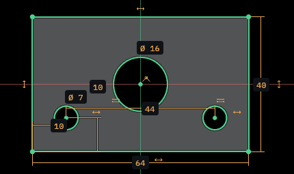
Editing one. Double clicking a sketch in the tree opens it the same way.
While editing, the view stays square to the sketch plane: pan, zoom and roll work, orbit and standard views do not.
Constraining to the model. A constraint or dimension tool pressed while the selection does not fit it yet stays armed (its button lit) and takes more picks: a click on the sketch adds an element, and a click on an edge of a solid adds that edge, or the vertex at its end when the click is there and the tool takes a point. Once two items are picked and fit, the edges are projected into the sketch as guides (an edge the sketch already holds is used again) and the constraint goes on: a distance from a point to a model edge, a point coincident with a model vertex, a circle tangent to a round edge. That is one undo step. Enter applies the tool to a single item, Escape or a right click puts it away.
Finishing. Done in the task panel's header, or Enter, ends the edit and returns to the workbench you came from. Escape in the view drops what is in progress first: a typed value, a half-drawn shape, the selection.
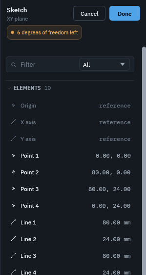
Datums
Design's datum tools add a plane, line, point or coordinate system to the active body. The task panel's Attached to list places it: on a base plane, or by a mode built from what is selected on the body. A mode whose picks are missing is greyed, its tooltip saying what to select first.
| Mode | Select first | Places it |
|---|---|---|
| On a face | A face | On the face, tangent to it where it is curved |
| Through three points, through two points | Edges or a face, if any | Through the points, the unpicked ones near the datum |
| Square to an edge, along an edge, tangent to an edge | An edge | At or along the edge |
| Where two planes meet | On the line two planes share | |
| Midway between two planes | Two faces | Halfway between parallel faces; between faces at an angle, on the plane bisecting it |
| Centre of a curve | A circular edge | At the circle's centre, square to it |
| Centre of mass | At the body's centre of mass, on its axes of inertia | |
| On a datum, another body's origin | On that datum or origin plane | |
| Square to a face | A face | Along the face's normal |
| Through a line and a point, where a line meets a plane | An edge | Through the line |
| Where two lines cross | Two edges | Where the lines pass nearest |
Each reference row in the panel swaps what the datum stands on: Use selected face or Use selected edge takes the current pick, and a plane row also takes a base plane or an earlier datum plane. The midway plane's two rows each take a face, a base plane or a datum plane, so it can stand between a face and a datum. Between faces at an angle it takes the bisector passing between them, through the material where they are two faces of one solid, its x-axis along the line where they meet.
References on the body's own solid follow it: when a feature before
the datum changes, the rebuild finds each face and edge again, by name,
and the datum moves with them, along with the sketches and features
built on it. The offset, turn, tilt and flip in the panel move the datum
from where its mode places it. pc.design.datum makes the
same datums from a script (Scripting).
Design features
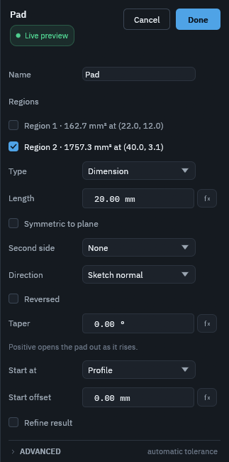
- A tool such as Pad adds the feature, hides the sketch it uses, and opens the feature's task panel.
- Changes in the panel apply to the model as you make them.
- Done keeps the feature. Cancel removes a new feature, or restores an existing one to how it was when the panel opened. Both sit in the panel's header, beside the feature's name and its state (live preview, rebuilding, or a failed rebuild).
Everything done in one task panel is one undo step. While the panel is open, the material the feature adds or takes away is drawn as a translucent preview.
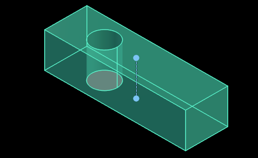
View handles. While its task is open, a feature shows a dot at the end of each number it can show in the view: a pad's or pocket's length (and the second side's), a hole's depth, a thread's length along its face, a revolution's or groove's angles on an arc round its axis, a draft's angle, a primitive's sizes, a fillet's radius or a chamfer's size. One more dot sets where it starts: a pad's, pocket's or hole's start offset, from its profile or from the plane or face it starts on, and a revolution's or groove's start angle; those go either side of zero. Drag a dot to set the number: in steps of 1 mm or 5°, or with Shift held in fine steps of 0.1 mm or 1° (Preferences › Design sets all four). A drag stops on a number's limit even where that is no whole step (a revolution's 360°, a draft's 45°, a fillet's largest size); only typing goes past one. Every number field in the app does the same: dragged, it stops at its range or limit, and the mouse wheel's steps land on it. The number shows beside the dot and the status bar names it with its steps while it is held. A pad's, pocket's, hole's, revolution's or groove's dot turns the feature the other way when clicked, or when dragged back through its start. A number a formula sets has no dot. A pad's or pocket's length snaps to a flat face square to its way, of any body shown, when its dot comes within a few pixels of that face's plane; the face lights while it holds, and Alt drags past it. While a dot is held, typing a number opens a field beside it; Enter sets it, and text that is no number sets the number's formula. The dot being edited is drawn lit: the one held, the one whose typed value is still open, or the one whose field the task panel last changed. A fillet's or chamfer's dot stands on its edges whether they were picked one by one, taken with their faces or all taken.
Number fields in task panels step with the mouse wheel over them: a whole unit a notch, a tenth with Shift.
Regions. A sketch's curves may cross, meet three or
more at a point, or leave a spur: every closed area between them is a
region (two overlapping circles make three, the lens and two crescents).
By default a feature takes them all, a loop inside another loop being a
hole. A pad, pocket, revolution or groove can take only some. Before
starting it, click a region of the closed sketch in the view to pick it
alone, and Ctrl+click to add or take away more: the feature starts with
exactly those, so a disc inside a ring picked together with the ring
pads the whole disc. A click on the sketch's lines, or on its row in the
tree, selects the whole sketch again. With its task open, click a region
on the sketch's plane to take it alone, Ctrl+click to add or take away
one; the regions left out show shaded. The task panel lists the same
regions as checks. A region keeps its name while the sketch's dimensions
change; pc.sketch.regions lists them for scripts, and the
feature's regions field holds the names it takes.
Ctrl+click on a curve of a closed sketch picks that curve beside its
regions. A revolution or groove started with a straight curve picked
turns about it (its axis set to that sketch line). A pipe started with
curves of a sketch picked runs along those curves alone, one chain of
them, and takes the body's latest other sketch as its profile; its task
lists the path sketch's curves as checks, every one ticked while the
pipe takes the whole sketch, and the feature's path_curves
field holds the ones it takes.
Where it starts. A pad, pocket or hole starts on its sketch's plane. Its Start at list moves the start to a datum plane of the body, the plane of another of its sketches, or Selected face (a flat face clicked in the view first). Start offset moves it on from there, either side of zero. A revolution's or groove's Start angle turns where it starts about its axis.
Primitives. The additive and subtractive primitives (the toolbar's Primitive lists) are a box, cylinder, sphere, cone, torus, ellipsoid, prism, wedge or tube: a hollow cylinder with an outer and an inner radius and a height, standing on its placement like the cylinder. A subtractive tube cuts a ring-shaped groove and leaves the core. A tube whose inner radius is not below its outer fails on the feature.
Keep what it shares. A pocket, a groove, and a loft, pipe or primitive that cuts, can keep only the material it shares with the body, cutting the rest away, instead of cutting its own shape out: tick Keep what it shares in its panel. A cutting helix has the same as Keep inside.
A tilted axis. A revolution, groove or helix can turn about an edge, a datum line or a borrowed edge that does not lie in the sketch plane: tick Project onto the sketch, and it turns about the axis's shadow on the plane. Without it, an axis that leaves the plane is refused on the feature.
Boolean tolerance. Every feature that fuses or cuts has an Advanced group under its panel with a Tolerance. Faces closer than it are joined by the fuse or cut, closing a small gap or sliver between them. Empty leaves it automatic, and Automatic puts a stated one back. It takes a formula, and the property panel lists it as Boolean tolerance.
Imported and converted solids take features too. The first feature added to one (a pocket, a fillet) gives the body a Base shape feature first: the imported solid, kept as what the body's history starts from. The body stays one body; its history reads Base, then the feature. Cancel on that first feature, or deleting the Base once nothing follows it, makes the body the plain imported solid again. Repair shape on such a body mends its base, and the features build again on it.
Replace shape… (a body's menu, in the tree or the view) reads the shape from another file: its first solid becomes the base, and the features after it build again on the new shape, finding their faces by name. On a body without features it simply replaces the shape. It clears the undo history, as an import does.
Fillet and chamfer work on the picked edges, or every edge of a picked face, and with nothing picked ask for a pick first. With Follow tangent edges on they take every edge that runs on smoothly from them too (the round of a filleted corner and the sides past it). A chamfer by two distances, or by a distance and an angle, measures its first distance on one face of the edge (Flip direction takes the other) and keeps it on that side all along a tangent chain, even where the faces change from a flat side to a round and on. A chamfer's Auto, a new one's, bevels its size each way, but a face too narrow for it takes the bevel only as far as it goes while the other face's leg goes on, edge by edge; its handle drags until every face has run out. A chamfer by two distances has a handle on each face, each stopping where its face runs out.
A fillet's Type is Auto for a new one: one radius, but on a single edge a face too narrow for it takes the round only as far as it goes, while the other face's contact goes on growing, the round turning elliptical, until that face runs out too; its handle drags that far. Radius is the plain round. Two distances meets one face Distance 1 from the edge and the other Distance 2 (Flip direction swaps the faces), with a handle on each face that stops where that face runs out. Its Profile is Elliptical, the round stretched to the two distances, or Conic, whose Rho sets how full it is: near 0 almost a bevel, 0.5 a parabola, near 1 almost the sharp edge. Two distances round several edges together where they run on from each other as one tangent chain, or meet three at a time at a box's corner; any other meeting of such rounds at a vertex is refused with the reason. A round over several edges has its handles on the first, each stopping where the nearest face of any edge runs out.
Variable runs the radius along the edges, taken as one run end to end: Start radius at one end, End radius at the other, smoothly between and never past them. Start from the other end turns the run round. + Radius between adds a radius at a place along the run, At its share of the run's length from the start (0.5 halfway), in the widest gap so far; × takes one away. The edges must make one run, a tangent chain or edges picked end to end; edges that branch at a vertex are refused. The radii are set in the panel only, as the view has no handle for a place along the run, and Corners does not apply.
Corners says how a vertex closes where the rounds or bevels meet. A fillet's Setback stops each round short of the corner and fills the gap with one smooth patch; Rolling ball runs every round into the corner, the rounds meeting along the curves where they cross and the ball's sphere or torus closing what is left, on corners of three edges between flat faces (other corners say so). A chamfer's Point mitres the bevels into one point; Facet ends them on a small flat facet, a triangle where three meet (not yet on a padded solid's corners).
Overflow says what a round or bevel does where it reaches more than its own two faces. Every switch is on at first, and the first that works is used; with none that works, the feature fails and says why.
- Blend into round: where it reaches a round already on the body, it bends to meet that round smoothly, with no step. A boss's foot round near a rounded edge of the block runs on into that edge round instead of stopping short of it.
- Hold edge: where the round would run over a sharp edge of the body, the edge is kept and the round rests on it. Hold edge at the end does the same where only the round's end runs over the edge.
- Trim through: the round keeps its own shape, and the faces it reaches are cut back or extended to meet it.
- Narrow gaps between rounds, across a face and across part of a face: where a gap is tighter than the radius (a slot narrower than twice the radius, a pocket's tight corner), each round runs on until the rounds meet. The first takes gaps made of rounds alone, the second also one whole face, the third also part of a face.
A chamfer has Blend into round and Trim through only. Every fillet along edges shows Overflow. A round of one radius takes every switch, with Setback or Rolling ball corners, and so does a Variable round holding one radius all along and Two distances that are equal with the Elliptical profile. A radius that varies, two different distances, the Conic profile and a rolling-ball corner joining convex and concave rounds take Trim through alone: the other switches change nothing there, and with Trim through off a round that would change another face fails and says so.
A fillet's Edges choice Between two faces rounds between two picked faces that need share no edge: the ball rolls between them, and the round fills or takes off what lies between it and where the faces' surfaces meet, such as a step from a tall block down to a low one across a groove.
A fillet's or chamfer's size never drags past what builds. When its task opens or its edges change, the largest size that builds on them is worked out beside the preview, and dragging the size, by its dot or in its field, stops there: in 1 mm steps with a largest of 5.3 mm a drag up goes 4, 5, 5.3 and back down 5.3, 5, 4. A chamfer by two distances keeps their ratio, so both sizes stop at the same scale. Only a size typed past the largest fails.
When a fillet or chamfer fails, its error names the edges that cannot take it ("edge 2 of 3: …"), they draw red while the feature is selected or its task is open, and the task lists them. The task also gives the largest size that fits every edge, with Use to set it, and what each failing edge takes alone. Leave these edges sharp (in the task and the feature's tree menu) takes the failing edges out of the feature in one step that undo puts back; the feature never builds part of its edges on its own.
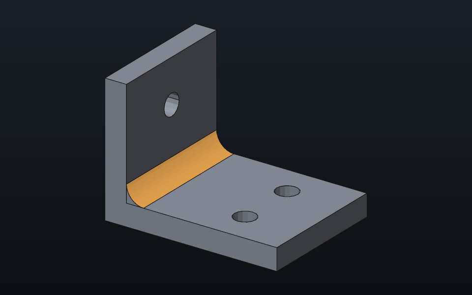
Delete faces takes picked faces out of the solid and closes each opening from the faces around it: a bore, a boss or a round taken away, on any solid, an imported one included. What the kernel does not close yet it refuses by name, on the feature.
Offset faces pushes or pulls picked faces along their outward normals (negative into the material; a bore offset in widens), and Move faces shifts them, or turns them about an axis; in both the faces around them follow on their own surfaces. The distance, the move and the angle take formulas.
Offset solid grows the whole solid by a distance, or shrinks it with a negative one: every face moves that far along its outward normal and the faces around it follow, corners staying sharp. A 10 mm box offset by 1 mm is 12 mm each way, and a hole in it narrows by 2 mm. Use it for a cavity with clearance (a body offset and cut from another with Boolean) or a socket with play. The kernel offsets flat, cylindrical, conical, spherical and toroidal faces; a solid with a free-form face (a spline pad, a loft, an ellipsoid), or one a shrink would collapse, fails on the feature with the kernel's reason.
Thread cuts a thread into a round face of the solid, a shaft's outside or a bore's inside, to a standard size or a pitch and depth of your own, for its whole length or part of it, with a chamfered start or a run-out end, or only shown as a cosmetic thread. docs/HOLES.md (Threads on a face) describes it.
Rib grows a web from an open line or chain of lines and arcs in a sketch, the classic stiffener between two walls of a printed part. Draw the line where the web's free edge goes, on a plane through the part (the middle of a bracket, across a channel), select the sketch and choose Rib. The line's ends run on along it until they meet the solid, and the web fills between the line and the solid on the side where the solid closes it in, Thickness thick: on Both sides of the sketch plane, or all of it on One side or the Other side. Along the normal instead thickens the line in its plane and runs it along the plane's normal until it meets the solid: a web drawn on a plane above a floor stands down onto it, and one drawn between two plates reaches both. Across the plane, a line drawn above walls shorter than it runs on over their tops: the web then fills down between them and onto their tops, ending square where the solid ends along the line, flush with the walls' outer faces. A line that meets no solid, or a sketch that closes, fails on the feature. A rib is copied by Mirrored and the patterns like any other feature.
Scale body scales the whole solid about a point: by one Factor, or with Per axis by one along each of the body's X, Y and Z. It scales About the body's origin, the middle of the solid's bounding box, or a datum's origin (a datum point, a coordinate system). The inch → mm preset sets the factor to 25.4 for a part modelled in inches, and mm → inch goes the other way. Equal factors keep a cylinder a cylinder; unequal ones stretch it into a free-form surface, which some later features (an offset) cannot take. (The Scaled pattern is another thing: copies of a feature, each larger.)
Project sketch onto faces carries a sketch along its plane's normal onto picked faces of the solid, flat or curved: a label or a logo on a cylinder's wall. Select the sketch in the tree (and the faces, or add them in the task), then choose the mode: Split lines divides the faces along the sketch's curves and leaves the solid as it is (faces later features and colours can take), Emboss raises the regions the curves enclose out of the faces by the height, and Deboss sinks them in. Put the sketch beside the faces rather than through the solid: each curve lands on the side nearest the sketch. Carried straight onto a round wall, the sketch keeps its look from in front, but on the wall its widths stretch toward the sides.
Tick Wrap onto the curved surface to wrap the sketch onto the surface instead. The sketch's middle lands where the straight projection would put it, and the rest is laid onto the surface from there.
On a cylinder or cone the sketch is unrolled, as a paper label goes on a can: every length in the sketch is the same length on the wall. Its width runs round the axis and its height along it (on a cone, along the slope). A rectangle as wide as the wall's circumference goes all the way round, so a band or a scale can wrap much further than a straight projection reaches. The sketch's plane must run along the axis, not across it; a sketch that would reach more than once round is refused.
A sphere, a torus or a free-form face cannot take a flat sketch without stretching it, so the sketch is laid on as a flat sheet: every length running out from its middle is kept, and lengths across those lines stretch with the surface's curvature, little for a label small beside the surface. On a sphere of radius 10 a 6 x 4 rectangle covers 23.8 mm². The picked faces must all lie on one surface.
Recognize holes reads the body's solid for round holes: full bores open at one end or both, ending flat or in a drill point. It deletes their faces (one Delete faces feature) and drills them again as Hole features, one per set of alike holes on one plane, from a hidden sketch of their centres, so a recognized hole's diameter, depth and point are numbers to change like any hole's. Bores it cannot describe (a counterbore, a countersink, a slot) are left as they are and counted in the log. On an imported solid it gives the body its base shape first.
Patterns repeat features (the selected one, else the body's last that adds or cuts): Mirrored across a plane (the features picked in the tree, several with Ctrl, or with the body itself picked the whole body; its Originals list changes it after), Linear pattern along a line, Polar pattern about an axis, Circular pattern in concentric rings (each ring stepped out from the axis by the ring spacing, with a count of its own), Point pattern at a sketch's points (a copy at each point after the first, moved by how far it is from the first, so the original belongs on the first point drawn), and Path pattern along a sketch's chain of curves or an edge of the solid. Linear and polar patterns take Uneven spacing or Uneven steps, a gap of its own from each occurrence to the next; over the overall length or angle the gaps must add up to it, or the pattern is refused. A path pattern spreads its occurrences over the whole path (evenly round a closed one) or spaces them a distance apart along it; the original stands for the path's start, or its end with From the path's end, and each copy moves from there to its place, turned as the path turns with Turn with the path. An edge is found again on the solid as it stands where the pattern does in the history, so the copies follow the edge when the features before it change. Multi transform chains steps of every kind, a path among them, each applied to every occurrence before it. Fill pattern covers a region with copies in a Grid (a spacing along the rows and one between them) or a Honeycomb (each copy one spacing from its six neighbours): for vents and lightening holes. The region is a sketch's area (its regions chosen as a pad's are) or a flat face of the solid picked in the view, its outer edge bounding it. The lattice passes through the original and runs along the sketch's x axis (the body's X laid on a face), turned by Angle; the arrows on the original drag the spacings. A copy is made where all of it lies inside, at least Margin from the edge, and with Trim at the edge the copies the edge passes through are made too, trimmed to the region. The copies are the original's tool built once and moved, put in by one boolean, so a few hundred holes build in a second or two; more than 2000 are refused, with the spacing to widen. With a mirror's or pattern's task open, a dot stands at each occurrence, the original among them; click one to leave it out or bring it back. A skipped one draws crossed out, and the panel's Skipped row lists them, each with a button bringing it back and Clear bringing back all.
Generators (the toolbar's Generators list) make a sketch from a few numbers, set in its panel or with formulas: an involute gear to pad, a chain sprocket to pad, a stepped shaft to revolve, and a shaft's keyway to pocket. Each asks for its plane as a new sketch does.
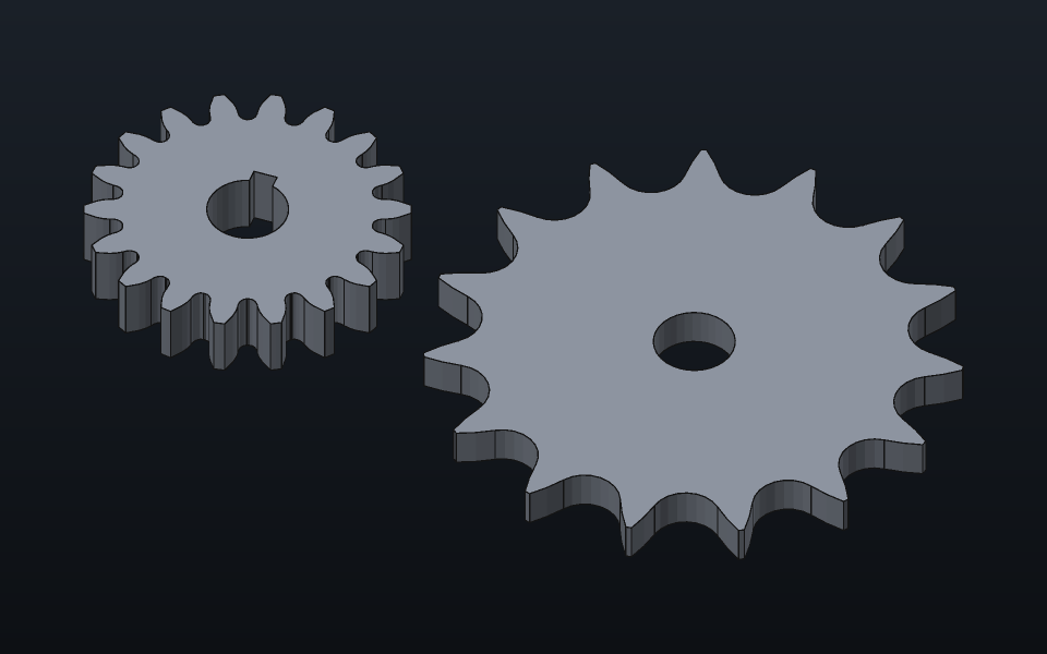
- A gear's root is the one a rack cutter leaves, its rounded tip tracing the root fillet; on a pinion of few teeth (below about 17 at 20°) the cutter undercuts the flanks above the base circle, and the panel says so. Root as the cutter leaves it off draws a root fillet arc instead (what gears made before had).
- Keyway in the bore cuts a parallel key's keyway into a gear's or a sprocket's bore. Its width and depth at 0 take the standard key's by the bore (DIN 6885, ISO 773, bores of 6 to 230 mm).
- The Keyway generator draws the key's slot, round ended or square, its width the standard key's for the shaft's diameter; the panel gives the depth to pocket it. Placed on the round face of a shaft, it runs along the shaft's axis.
- A gear or a sprocket takes 3 or 5 teeth at the least and 500 at the most. Numbers that make no shape (a negative keyway size, sizes so large the curves overflow) are refused with what to change, and the sketch keeps what it had.
Split… (a body's menu, in the tree or the view) cuts
a body into two pieces, each a body of its own: a part bigger than the
bed, or one that prints without supports in two halves. It cuts across
the middle of the solid, square to its longest side, and opens the first
piece's task, where Cut by is a plane (a base plane, a
datum plane or a sketch's plane of the body split, or a picked face)
moved by Offset, or a sketch of the body whose profile
is carried through the whole solid. The pieces build as the cut changes;
Cancel takes them away. Each piece starts with a Clone of the body split
and a Split feature keeping its side (in front of the plane or inside
the profile, or with Keep the other side the rest), so
editing the body split rebuilds the pieces. The body split is hidden,
and the pieces stand where it stood. A change to one piece's cut is made
to every piece of the split. From a script,
design.split.
Separate pieces (a body's menu, in the tree or the
view, offered when its solid is in more than one piece) makes each piece
a body of its own: a plate pocketed through into two, a set of parts
modelled in one body. Each piece starts with a Clone of the body and a
Piece feature keeping the solid nearest a point on that piece, so
editing the body rebuilds them; the body itself is hidden and the pieces
stand where it stood. An edit that changes how many pieces there are
does not add or remove bodies: each keeps the piece nearest its point.
From a script, design.separate.
Section across X, Y or Z to sketch (a body's menu,
in the tree or the view) cuts the solid with a plane through its middle,
square to that axis, and keeps the outline as a new sketch on the plane,
in a body of its own placed where the cut body stands: the outer
boundary and every hole, each curve exact (lines, arcs, circles,
ellipses, splines) and their ends joined, so a closed cut pads or
pockets as drawn. The sketch is taken once and does not follow the
solid. From a script, design.section takes any plane (a
base plane, a datum plane or a sketch's plane) with an offset, and makes
several parallel cuts with count and spacing,
each a sketch of its own.
Borrowed geometry brings another body's sketch, or
faces and edges of its solid, into this body, where the two bodies sit
(Borrow geometry in Design; design.borrow). It follows its
source, or keeps a frozen copy. A borrowed face is:
- a pad's or pocket's profile, when flat
- the face a pad or pocket stops on (Up to its name in the Type list)
- one of the faces an Up to shape side stops on (its Borrowed stop faces ticks), beside picked faces of the body's own solid; with only borrowed faces it needs no earlier material
- the face a revolution or groove turns until (Up to its name in the Type list), on the first feature too
- the plane of a new sketch (select the borrow, then New sketch), or
of an existing one: a sketch's tree menu offers Map onto each flat face
its body borrows (
design.map_sketch). Either way the sketch follows the face as its body changes or moves.
A borrowed edge is an axis to turn about, a direction to pad along, or a pipe's path.
The tree
- Double clicking a feature opens it for editing in the workbench that owns it.
- The eye on a row shows or hides a feature, a body or an imported part.
- Isolate (View › Isolate selection, a body's menu in the tree or the view) shows only the selected bodies, a hidden one among them, without touching any eye: it is a way of looking, not an edit, so it is no undo step and the file keeps what it showed. A card at the bottom of the view names what is isolated; its Show all, Escape or Isolate again puts back what was shown. Export and the slicer take what the view shows while it lasts. Hide the others (a body's tree menu) hides every other body for good, as one undo step.
- A feature's right-click menu offers edit, rename, its body's appearance and placement, suppress, hide, move up, down or after another, set or clear the tip, freeze the body, cut, copy, paste, delete, copy and paste formulas, recompute and properties. A body's menu, in the tree or the view, offers appearance, placement, freeze, make unselectable, linked copy and the rest. Features after the tip are shown muted and are not built.
- Selecting a feature shows its body as it stands there: the tip moves to it (back to the whole history when it is the last), later features are muted, and a feature made then goes in right after it. Moving through history this way is not an undo step.
- Pointing at a feature's row, or selecting it, tints the rows of the features that use it (a sketch's pads and pockets); a selected feature tints its inputs too (a pad's sketch).
- A thin green bar under a body's tip row (under the last feature when the whole history builds) marks where the body stops. Drag it up or down the history: the tip follows the row under the pointer and the view shows the body as it stands there, the rows past it muted. Like selecting a feature, this is not an undo step.
- Appearance, placement and moving in history open in the task panel: the view shows each change at once, Done keeps it as one undo step and Cancel puts back what was there.
- The Placement task's Move by group moves a body by numbers from where it is now. Relative to picks the axes the numbers follow: World, another body's, or a datum's. Turn about picks the point it turns about: Body origin, Middle of its box or Centre of mass. Set Along X, Y, Z and About X, Y, Z, then press Move.
- Deleting a body removes its features. Unless the body was still empty, this clears the undo history.
- Array of copies… (a body's menu) repeats the body in a row (a count, a spacing and a direction), a ring (a count, the angle between neighbours and an axis), along a path (a sketch's chain of curves or a selected edge of a solid: the copies spread over its whole length or a spacing apart, measured along it, and turned with it when asked) or at points (a sketch's points that are no curve's end or centre; the body stands at the first), each repeat a linked copy the array owns. A component's tree menu offers it too: every body in the component is copied, each occurrence's copies held together in a rigid component of their own beside it, and deleting one of them skips the whole occurrence. While the task lays out a row, an arrow stands on its first copy: dragging it changes the spacing (in 0.1 mm steps, Escape puts it back). A path or point array reads its places when it is made or edited. The copies follow every change to the body and stand where the array puts them from where the body sits, so moving the body carries them. They draw, pick, export and print like any body, and the parts list counts them with the body. The tree gathers an array's copies under a row of its own (its eye hides them all, Delete takes the array away and leaves the body) and names each copy's place in it; Edit array on that row, the body or a copy changes the count, spacing, angle or axis in the task panel, one undo step, and deleting a copy (or Skip this copy) leaves that place out until Edit array brings it back.
Notes
A note puts a line of text on a face, an edge or a point of a body: a
leader from the point to a label that reads its number and text
(#3 Round this edge). There are two ways to make one:
- Note in the view toolbar (beside Measure) arms the note tool. Click the part: on an edge the note goes on that edge, elsewhere on the face. A card by the point asks for the text; Enter puts the note down, Escape drops it. Clicking a note with the tool armed opens its card again, to reword it, answer its question, resolve or reopen it, or delete it.
- Add note in a body's menu opens one in the task
panel: from the view's menu it stands at the point you right-clicked,
from the tree's somewhere on the body. The panel sets the
Text (text starting with
=shows what a formula comes to, as=Pad.lengthdoes), places the Label from the point in the body's own axes, and shows or hides it.
A note moves with its body and follows its face or edge when the body is rebuilt. When an edit takes that face or edge away, the note is lost: it stays where it was, drawn red, and its tree row says Lost. A note on a spot the part hides from the view draws faint, its leader dashed. Each note keeps its number; a note taken away leaves its number unused.
The tree lists a body's notes under it, in an Annotations row: a
resolved note is crossed out, a question still open shows
?. A double click or Edit note… opens one
in the task panel, Open card on its card,
Resolve and Reopen mark it, and its
eye hides it. View › Annotations shows or hides every note at once (the
note tool shows them while it is armed). A STEP export carries the shown
notes with their text, on the faces they point at. How an agent reads
and answers notes is in AI agents.
Rebuilding
- Changing a feature marks it dirty, along with everything that depends on it. Editing a sketch dirties the features built from it.
- Each frame, every body with a dirty feature is rebuilt on the kernel's threads. A body builds one plan at a time; changes made meanwhile wait, and only the latest one is built.
- A failed rebuild marks its feature in the tree and in the task panel, and logs the error. The body shows the history before the failure.
- A row with a problem ends in a chip naming it: Failed, Not built (a feature before it fails), Formula (a formula it reads fails), Input broken (a feature it reads fails), Needs package, Warning (its bench warns of something, such as projections whose source is gone, a face found by where it was picked once its name was lost, or a feature that adds or removes material and left the solid as it was: a pocket pointing away from the material, a pad buried inside it, a copy landing past it), Broken shape or Stale link. Hover the chip for the whole reason; a click opens it in a window you can copy from. The tree's header counts the problems, and a click on the count selects the next one, opening the branches above it and scrolling to it.
- Recompute (Edit › Recompute, or its button on the status bar) rebuilds every body.
Undo
Undo steps back through the recorded edits by applying their inverses. Each mouse gesture or command is one step, and the history keeps 64 steps. In a sketch's editing session every edit (a line drawn, a constraint added) is a step of its own. Imports, deleting a body that has anything in it, Replace shape, converting a mesh, refining and repairing a shape clear the history.