 printCAD
Holes
Design's Hole (Shift+H, with a sketch selected on a body that has a
solid) drills at every circle centre and lone point of the sketch,
construction geometry left out. With no sketch selected and a flat face
of the solid clicked, it drills where you clicked, from a hidden sketch
of its own on that face; add points to that sketch for more holes. It
starts as a custom hole the size of the sketch's circles (the most
common size when they differ, which the log says; 5 mm for a sketch of
points alone), 10 mm deep, drilled against the sketch's normal;
Reversed drills the other way. The task panel sets the
rows below; a script sets the same fields by name
(pc.design.hole, pc.design.set).
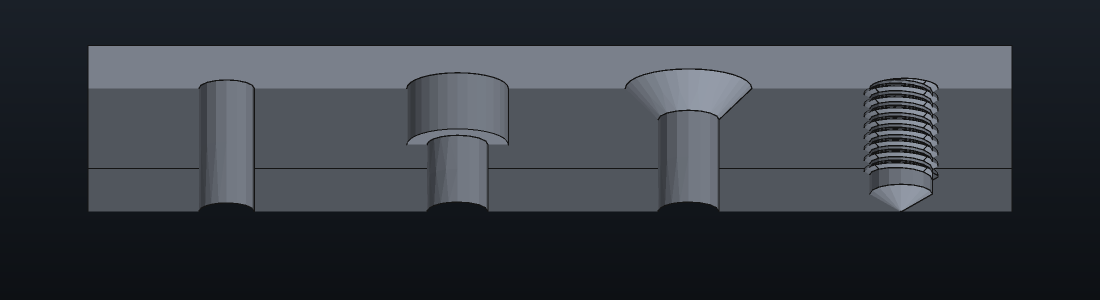
Size
Standard is Custom (a plain diameter) or a thread standard:
| Standard | Sizes | Form |
|---|---|---|
| ISO metric coarse, fine | M1.6 to M48, M3x0.35 to M36x3 | 60° |
| UNC | #1 to 1 inch | 60° |
| UNF | #0 to 1 inch | 60° |
| UNEF | #12 to 1 inch | 60° |
| BSW | 1/8 to 1 inch | 55° |
| BSF | 3/16 to 1 inch | 55° |
| BSP parallel (G) | 1/16 to 2 | 55° |
| BSP taper (Rc) | 1/16 to 2 | 55°, 1:16 taper |
| NPT | 1/16 to 2 | 60°, 1:16 taper |
A sized hole drills the tap drill when Threaded (tap drill) is on, otherwise the clearance of its Fit (close, normal, loose: ISO 273 for metric sizes, ASME B18.2.8 for unified ones; the other standards drill the major diameter), or Custom, a clearance diameter of your own. A tapped taper thread drills the thread's minor diameter at the face and narrows 1:16 on the diameter from there.
Class is the internal thread's class: 4H to 8H and 4G to 8G for metric (a G class moves the diameters out by the ISO 965-1 allowance, (15 + 11 P) µm), 1B to 3B for unified, Medium or Normal for Whitworth. Pipe threads have none. Left-hand thread turns a modeled thread the other way.
Modeled thread (offered once Threaded is on) cuts the thread itself into the wall, for printing it rather than tapping it: the standard's flank angle, out to its major diameter, along a cone for a taper thread. Thread length is Depth given (the Thread depth row), the Whole hole, or the hole Less the run-out of three pitches a tap leaves at the bottom. A through hole threaded its whole length (or less the run-out, which a through hole has none of) runs as far as the solid reaches along the hole's axis, out past the far side.
Cosmetic thread (on a threaded hole that is not modeled) keeps the bore at its tap drill and shows the thread instead: a helix of the thread's pitch down the bore, as far as the hole goes (a through hole's to where it leaves the solid), and the designation in its row's tooltip in the tree ("Hole · M6 thread"). The designation is also a callout at each bore's mouth under View › Annotations, a column of the Assembly's parts list ("2 × M6 thread") and of its CSV, and a callout (its text and its leader) in a STEP export, naming the bore it threads so a reader puts it on that part. No groove reaches an export: drill the tap size, print, and tap the hole afterwards.
A mirror or pattern of the hole, or of the whole body, threads each copy it makes the same way, cut to the same hand across a mirror, and counts it in the parts list and the export. A copy that lands off the material is not threaded. A path pattern's and a fill pattern's copies are not threaded yet, since only the built solid says where they fall.
Depth and bottom
Through all or a Depth. A blind hole's Drill point is flat or angled (118°, 135° or any Point angle from 10° to 170°); Point within the depth makes the depth run to the tip rather than to the end of the wall. Taper leans the wall in toward the bottom, up to 44° either way (a tapped taper thread uses its own).
Start at is where drilling starts: the sketch's own plane, a datum plane, another sketch's plane or a flat face of the solid (click it, then pick Selected face), the circles carried along the drill to it. A face is found again on the solid before the hole, so the hole follows it when the features before it change. Start offset starts that much further into the material, or above it when negative.
While the task is open, two handles in the view stand on the first centre of the sketch: one drags Start offset along the drill and the other the Depth (none for a hole through all). They work as every feature's view handles do; see View handles under Design features in EDITING.md.
Hole cut
- Counterbore: a wider bore, diameter and depth.
- Spotface: a shallow counterbore, to face a seat.
- Countersink: a cone, diameter at the face and included angle (90° when a script leaves it out).
- Counterdrill: a wider bore ending in a cone down to the hole: diameter, depth and the cone's angle (118° when a script leaves it out).
The seats below are offered only for a hole sized from an ISO metric thread, and a size the seat's table lacks says so in the panel.
- ISO 4762 seat: the counterbore for a socket head cap screw of the hole's metric size (DIN 974-1 diameters).
- ISO 10642 seat: the 90° countersink for a countersunk socket screw of the hole's metric size.
- ISO 7380 seat: the counterbore for a button head screw.
- ISO 2009 seat and ISO 7046 seat: the 90° countersink for a slotted or cross recessed countersunk screw.
- DIN 7984 seat: the counterbore for a low head cap screw.
- ISO 4762 + washer seat: the counterbore for a socket head cap screw on an ISO 7089 washer (DIN 974-1's wider row).
- ISO 4017 seat: the counterbore for a hex head screw, with room for a socket wrench (DIN 974-2).
Nut trap
Nut trap cuts a hexagonal pocket at one end of the hole that holds a nut captive, beside any hole cut. It is sized from the nut of the hole's ISO metric thread; PRINTING.md has the sizes, the clearance, the depth and the side it sits on. A hole sized otherwise takes a nut trap of its own size.
For printing
The Printing section shapes a hole for the printer.
Shape is the bore's outline across its axis:
- Round: a plain circle.
- Teardrop: the circle with a point on its upper side, for a hole that prints lying down. The point's sides are tangent to the circle and lean the Point angle (45° by default) from the way it Points to, so its roof prints as two slopes rather than an overhang.
- Flat top: the teardrop cut off flat at the circle's top: a short bridge between the slopes, with the bore no taller than round.
The point faces the body's +Z, the build direction, unless you choose another axis. The shape is the drill's, and a counterbore's, spotface's or counterdrill's bore takes it too; a countersink and a drill point stay round. A hole drilled along its up direction has no side for a point, and says so. A mirror or a pattern turns the point with the copy.
Bridge layer leaves a thin layer (0.2 mm by default, a layer or two) across the hole at the floor of its counterbore, spotface, countersink or counterdrill. Printed with the cut facing down, the cut's floor is then one bridge across its whole width rather than a ring hanging round the hole. Drill the layer out after printing. A hole with no cut has no floor to bridge, and says so.
pc.design.hole{sketch = s, diameter = 5, through_all = true, shape = "Teardrop"}
pc.design.hole{sketch = s, diameter = 3.4, through_all = true, bridge = 0.2,
  cut = {Counterbore = {diameter = 6.5, depth = 3.4}}}
shape is "Round", "Teardrop"
or "FlatTop", or a table for more:
shape = {FlatTop = {angle_deg = 40, up = {0, 1, 0}}}.
Your own cuts
Cuts you use often go in hole_cuts.json in the
application's configuration folder (~/.config/printcad/ on
Linux, beside settings.json). It is read once a run, the
first time a hole lists its cuts; its profiles are listed under the
standard cuts, and picking one copies its sizes into the hole. Screw
seats and None are left out of it, since a seat needs the
hole's size.
{
  "profiles": [
    { "name": "M3 heat insert", "cut": { "Counterbore": { "diameter": 4.2, "depth": 5.0 } } },
    { "name": "Deburr 6", "cut": { "Countersink": { "diameter": 6.0, "angle_deg": 90.0 } } },
    { "name": "Stepped 8", "cut": { "Counterdrill": { "diameter": 8.0, "depth": 3.0, "angle_deg": 118.0 } } },
    { "name": "Face 12", "cut": { "Spotface": { "diameter": 12.0, "depth": 0.5 } } }
  ]
}
Scripts
pc.design.hole{
  sketch = s,
  depth = 8,
  thread = {standard = "Unc", size = "1/4-20", class = "3B", left_handed = false},
  threaded = true,
  drill_point = {Angled = {angle_deg = 118}},
  cut = {Counterdrill = {diameter = 9, depth = 2, angle_deg = 90}},
}
standard is one of IsoMetricCoarse,
IsoMetricFine, Unc, Unf,
Unef, Bsw, Bsf,
BspParallel, BspTaper or Npt;
size is the designation the panel lists. A size alone,
thread = "M6" or thread = "1/4-20", takes the
first standard that has it. A drill point is
drill_point = {Angled = {angle_deg = 135}}, or
{Angled = {}} for 118°. A screw seat is
cut = {Seat = {seat = "SocketHead"}}, or
"Countersunk", "ButtonHead",
"SlottedCountersunk", "CrossCountersunk",
"LowHeadCap", "CapScrewWithWasher",
"HexHead". clearance sets a clearance of your
own. modeled_thread = true cuts the thread (with
threaded = true), its length from
thread_length, "Given" (with
thread_depth in mm), "HoleDepth" or
"RunOut"; cosmetic_thread = true (on a
threaded hole, modeled_thread off) shows the thread
instead, the bore left at its tap drill. nut_trap = true
adds a nut trap at the mouth; a table sets it:
nut_trap = {side = "Bottom", clearance = 0.4, depth = 3, across_flats = 7, turn_deg = 30, standard = "Din934"},
each field left out taking its usual value.
start = {offset = 2, at = plane} starts it 2 mm in from a
datum plane or a sketch;
start = {face = {point = {x, y, z}, normal = {0, 0, 1}}}
from a face. face_point = {x, y, z} and
face_normal in place of sketch place one hole
on a flat face at that point.
Holes already in a solid
Recognize holes
(pc.design.recognize_holes) turns the round bores of a
body's solid, imported ones included, into Hole features: their faces go
in one Delete faces feature, and each set of alike holes on one plane is
drilled again from a hidden sketch of their centres. Bores it cannot
describe (counterbores, countersinks, slots) stay as they are.
Threads on a face
Thread (Design's subtractive group) cuts a thread into a round face the solid already has: a bolt's shank, the outside of a jar's neck, the inside of a cap, or a bore no Hole made. Click the face and choose Thread; which way the face faces tells an external thread from an internal one. The task panel shows what it found (a shaft or a bore, its diameter and length) and sets:
- Standard and Size, as a hole's (the taper standards are a Hole's, since only a Hole tapers its bore): the thread's pitch, and its depth from the major to the minor diameter. The tool starts with the ISO metric coarse size nearest the face, by its major diameter on a shaft and its minor in a bore. Custom cuts a Pitch and a Depth of your own, 60° between the flanks. The face is not resized: model a shaft at the major diameter and a bore at the minor.
- Whole face, or a Length from the end the thread starts at. It starts at the end of the face nearer where you clicked; From the other end starts it at the far one. While the task is open the length has a drag arrow along the face.
- Left-hand thread.
- Chamfer the start: a 45° chamfer at the starting end, down to the thread's root on a shaft and out to it in a bore, so the first turn starts cleanly and prints without a ragged edge.
- Run out at the end: the groove grows shallower over its last two pitches instead of ending square, as a die leaves it.
- Cosmetic thread: nothing is cut. The face shows a helix of the thread's pitch, and the designation goes where a hole's cosmetic thread's does: the tree row's tooltip, View › Annotations, the parts list and a STEP export's callouts.
The groove is the same as a modeled hole thread's: the standard's flank angle, flat a pitch's eighth wide at its root, swept along a helix about the face's axis and kept within the face's length, so a thread running the whole of a shank stops square at the head's face rather than cutting into it. A face that is not a cylinder fails on the feature.
pc.design.thread{body = body, face_point = {5, 0, 8}, face_normal = {1, 0, 0},
  thread = "M10", full_length = false, length = 12, chamfer = true}
thread = "Custom" with pitch and
depth cuts a thread of your own.