 printCAD
Printing
What printCAD offers for the step from a model to a printer: the parts list's printing columns, nut traps for captive nuts, and the print layout that lays every part flat on the bed for export or the slicer. The bed itself (its size, where its origin is, whether it is drawn) and the slicer command are set in Preferences › 3D printing; Print bed on the view's pill, or View › Print bed, shows or hides it.
Printing columns
The Assembly's Parts list (B) carries three columns for printing beside the count and size of each part:
- Print: how many of the part to print. It starts at one per body of the part (a part that is bought starts at none); type another count in the cell to print spares or fewer. Clearing the cell goes back to one per body. The count is the whole part's, however the list is grouped. Linked copies and an array's copies share their source's shape, so they are bodies of its part and each adds one to its Print count (a skipped copy adds none). A mirrored copy has a shape of its own and is a part of its own.
- Volume: the volume of one piece. A solid's is the kernel's exact measure, worked out away from the window and kept until the part's shape changes (the cell shows … meanwhile); a mesh body's is the volume its triangles enclose.
- Mass: the filament one piece takes, its volume at the density of the material it is printed in.
Printed in under the list picks the material: PLA
(1.24 g/cm³), PETG (1.27), ABS (1.04), ASA (1.07), TPU (1.21), Nylon
(1.14) or PC (1.20), or Custom with a density of your own. It is kept
with the document. A body given a material of its own (Appearance, or
doc.set_body) is weighed at that material's density
instead.
The line under the list adds it up: how many pieces, their volume and the filament they take. Copy as CSV and Save as CSV carry the Print, Volume (cm³) and Mass (g) columns too.
A Threads column beside them names each part's cosmetic threads by designation and count ("2 × M6 thread"), the screws or inserts it takes: see HOLES.md for the threads and ASSEMBLY.md for the rest of the list.
From a script, asm.parts answers print,
volume, mass and density for each
part, asm.part{body = ..., print = 3} sets a count and
asm.print_material{name = "PETG"} the material (a name of
your own needs its density).
Text on a face
Design's Text on faces writes a label on the part in
one step: click the face, pick the tool, and type in its task. Its
Mode buttons raise the text out of the face, sink it
in, or only imprint it, by its Height;
Size, Spacing, Angle,
and Across and Up (mm its middle moves
on the face) place it. On a cylinder or a cone the text wraps onto the
face (on by itself there): its Wrap buttons lay it
round the axis, up it, or spread evenly round the whole cylinder, the
gap across the back as wide as the rest; the lit one clicked again lays
it flat, carried straight along the face's normal, which suits a flat
face. A {formula} in the text shows its value, so a serial
or revision number follows its variable, and Size,
Spacing, Angle,
Across and Up take formulas as any
feature's numbers do. A size of zero or less is an error on the
feature.
The text is written in a sketch of its own, hidden under the feature and standing 2 mm off the face: open it from the tree to lay the text out in a frame or along curves. A size, spacing or angle a formula sets on the feature sets the sketch's too, so the sketch shows the text as it builds; the sketch keeps the Across and Up typed in the task, and the build moves the text to where their formulas put it. Deleting the feature takes its sketch with it.
Text laid flat on a curved face has nowhere to land past the part's outline as seen from the front.
Nut traps
A Hole's Nut trap (in the Hole task, under the hole cut) cuts a hexagonal pocket at one end of the hole for a nut to sit in captive, so a screw turns into it from the other side.
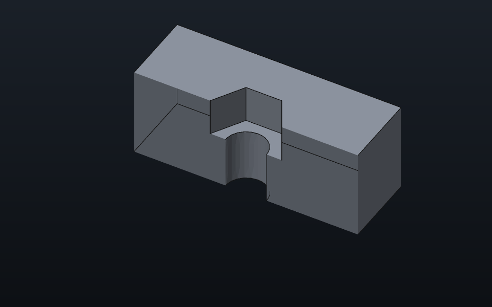
- Nut: the standard the pocket is sized from, by the hole's ISO metric thread size: ISO 4032 (the usual hex nut) or DIN 934 (17, 19 and 22 mm across the flats for M10, M12 and M14 where ISO 4032 has 16, 18 and 21). Own size takes an across-flats of your own instead, for any hole, a thread of another standard included.
- Nut clearance: added to the nut's across-flats and to its thickness, 0.3 mm unless set, so the nut drops in. Printers that print holes small want more.
- Own depth: a pocket deeper or shallower than the nut and its clearance.
- Nut side: Top puts the pocket at the hole's mouth, where the hole starts: on its sketch's plane, or where Start at and Start offset move the start to. Bottom puts it where the hole ends, its floor at the hole's depth: a nut buried in the part, set in by pausing the print at the layer above the pocket. A hole through all has no end to measure from, so a pocket at its bottom asks for the hole's depth instead; to trap a nut on the far face of a plate, give the hole the plate's thickness as its depth.
- Nut turn: the hexagon turned about the hole's axis; at 0 a corner points along the sketch's X. Turn it 30° to lay a flat along X, which prints a cleaner pocket roof when the hole lies on its side.
The panel says what the pocket comes to, or why it cannot be cut (no
metric size, a pocket no wider than the hole, one deeper than the hole).
A nut trap's clearance, depth, across-flats and turn take formulas
(Hole.nut_clearance, Hole.nut_depth,
Hole.nut_across_flats, Hole.nut_turn).
ISO 4032 across flats and thickness, mm:
| Size | M2 | M2.5 | M3 | M4 | M5 | M6 | M8 | M10 | M12 | M16 | M20 |
|---|---|---|---|---|---|---|---|---|---|---|---|
| Across flats | 4 | 5 | 5.5 | 7 | 8 | 10 | 13 | 16 | 18 | 24 | 30 |
| Thickness | 1.6 | 2 | 2.4 | 3.2 | 4.7 | 5.2 | 6.8 | 8.4 | 10.8 | 14.8 | 18 |
From a script, nut_trap is a field of
design.hole: nut_trap = true for the usual
pocket at the mouth, or a table,
{side = "Bottom", clearance = 0.4, depth = 3, across_flats = 7, turn_deg = 30, standard = "Din934"},
each field left out taking its usual value.
Hollow parts
Design's Thickness hollows a solid into walls of a set thickness. With faces picked it opens them: an open box from a block with its top picked. With no face picked it seals the hollow, a closed shell: a resin part printed hollow to save material, or a light FDM part. A resin print needs a way out for the liquid trapped inside; add a hole or a small pocket through the wall after the Thickness as its drain. The walls go inward by default; Inward off puts them outside the solid, which becomes the cavity, and Both sides puts them on both.
Print layout
The layout lays out bodies, not the pieces inside one: a body whose solid is in several pieces is one part. Separate pieces on its menu makes each piece a body of its own, laid out and counted on its own.
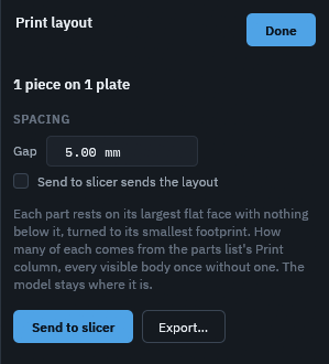
File › Print layout… (also in the command palette) lays every part to print on the bed, as many copies as the parts list's Print column asks for, and shows them there in the view while its task is open. Nothing moves: the model is back where it was when the task closes, and the layout is only where export and the slicer put the copies.
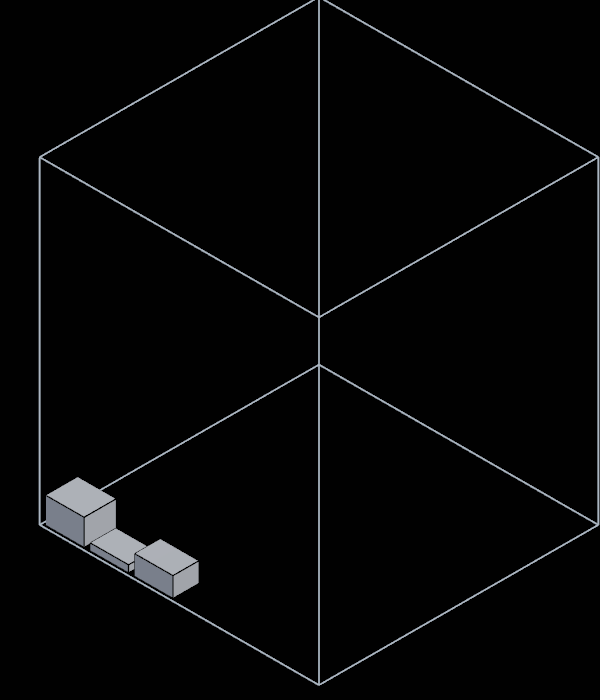
- Which parts, how many: each part of the parts list with a count to print above none and at least one visible body. A document whose benches keep no parts list prints every visible body that is not bought, once.
- How a part lies: on its largest flat face that the whole part stands on, no point of it below that face's plane; among faces within a hundredth of that area, the one leaving the part lowest. A part with no such face (a sphere) keeps the up of its own frame. It is then turned about the vertical to the smallest rectangle around its footprint, the rectangle's longer side along X.
- Choosing how a part lies: a body's menu in the view, opened on a flat face, has Print on this face: the layout turns that face down on the bed, then turns the part about the vertical as above. Print as modelled drops the part to the bed as it is modelled, unturned, its lowest point on the bed. Print on its best face gives the choice back to the layout. The task lists every part under Lying on the bed with the same choice, and Selected face down turns down the flat faces selected before it opened. The choice is kept with the body in the document and undoes like any edit. A chosen face the body no longer has, or one a rebuild made curved, leaves the part on its best face, and the task names it.
- How copies pack: in rows along X, the deepest footprints first, each row as deep as its first copy, the Gap (5 mm unless set) between copies and half of it from the bed's edges. A copy that fits only turned a quarter goes turned. What one bed cannot hold starts another plate, drawn beside the first along X.
- What does not fit: a part wider or deeper than the bed goes on a plate of its own, and one taller than the build height is named too, as is a part not built yet, which is left out. Split… on its body's menu cuts it into pieces that do fit (Editing › Design features); the pieces are parts of their own and the body split, hidden, is left out.
The bed is the one in Preferences › 3D printing (its width, depth, build height and whether its origin is the centre).
The task's Send to slicer writes the layout in the slicer's format and opens it in the slicer; Export… opens the export dialog set to Laid out for printing, which the dialog offers at any time. Send to slicer sends the layout (or Preferences › 3D printing › Send the print layout) makes File › Send to slicer (Ctrl+P) send the layout always. With several plates, the file holds them all, side by side.
From a script, pc.doc.print_layout{} answers where each
copy goes (its body, name, plate, bounds on the bed and the transform
from the body's own frame), with bed = {x, y, z} and
gap to lay out for another printer;
pc.doc.set_body{body = ..., print_on = 3} lies a part on
its face 3 (as pc.doc.faces numbers them),
print_on = "as_modelled" drops it unturned and
print_on = "auto" gives the choice back;
pc.file.export{path = ..., layout = true} writes the layout
and pc.file.send_to_slicer{layout = true} sends it.
Files for the slicer
File › Export (Ctrl+E) writes the visible bodies, or with Selected body only the selected ones, as STEP, STL or 3MF. A file per body writes each body in a file of its own instead, named after the body, into a folder it asks for; laid out for printing, each copy gets its own file ("Bracket 1", "Bracket 2"). Files of the same name already in the folder are replaced, each written whole or not at all, as every export is.
File › Send to slicer (Ctrl+P) writes the visible bodies to a file of the slicer's format and opens it in the slicer. Send selection to slicer (File menu and command palette) sends only the selected bodies; when the layout is sent, it lays out only their parts.
From a script,
pc.file.export{path = folder, per_body = true} writes a
file per body and answers each file's path in files, and
pc.file.send_to_slicer{selected = true} sends the
selection.
A 3MF names each body's object after it and carries the colour the body shows in; a face given a colour of its own, or imported with one, keeps it, so the slicer shows the bodies as the view draws them. STL carries no colour.
Overhangs
Before printing, Inspection's Overhangs shows which surface the printer cannot lay down without support: everything leaning out past the limit (45° by default) paints hot, and the legend says how much of the surface that is. Turn the body to try another orientation; see Inspection.
Fit check
A housing for something that exists (a device, a shaft, a bearing) can be checked against its scan before printing: place the scan in it and Inspection's Fit check paints where the two interfere and how much gap is left everywhere else; see Inspection.
Clearance
A part that fits over or into another needs play between them. Design's Offset solid grows or shrinks a whole body by a distance: offset a copy of the inner part by the clearance (0.2 to 0.3 mm suits most FDM printers) and cut it from the outer one with Boolean, and the cavity keeps that gap all round (Editing › Design features).
Compensation from a scan
A print rarely comes out the size it was drawn: plastic shrinks as it
cools, more across than up or the other way. Scan the print, align it
onto the body it was printed from (Inspection's Best fit), and
pc.inspect.compensation{scan = …, reference = …} reads how
each axis came out. Each scan point's distance to the model is explained
as each axis stretching about the model's middle, plus a leftover shift,
by least squares. A support's remains and other defects (points past
three times the fit's RMS) are left out.
stretch is each axis's stretch in percent (−0.5 is a
print 0.5 % small), and compensation the factors to scale
the model by so the next print comes out as drawn.
tie_xy = true fits one stretch for X and Y together.
rms_before and rms_after show how much of the
difference the stretch explains: what is left is warp, flare at the
first layer, and the scanner's own noise.
The fit reads more than the axes. Scan points on the walls of the
model's round holes and of its bosses and pins each add one unknown, the
radius error of that kind beyond what the stretch explains:
holes and bosses give
radius_error (a hole printing 0.1 mm small in radius reads
−0.1) and offset, the radius change to draw them with. The
side walls of the first 0.6 mm are left out of the fit and read against
it afterwards: flare is how far they stand out (the
elephant's foot). warp reads the bottom face:
flatness, lift (how high its highest part
stands over its middle height, a corner come off the bed) and
at, where. The model is read as it stood on the bed, +Z
up.
To print with it,
pc.app.print_compensation{x = c.compensation.x, y = c.compensation.y, z = c.compensation.z, holes = c.holes.offset, bosses = c.bosses.offset, from = "PLA on the Mk4"},
or Preferences › Printing › Shrinkage. STL, 3MF and Send to slicer then
draw each solid's round holes and bosses that much larger in radius (the
kernel offsets their faces, the neighbours following) and scale each
body about its middle by the factors; the log says by how much. A mesh
body is only scaled, and STEP still writes the bodies as drawn.
Make up for shrinkage turns it off and on.
The start page's Calibration coupon, or
pc.doc.coupon{}, makes a test part to measure it from:
holes and pins of graded sizes on a plate, a ladder of narrow slots and
a fan of overhangs from 30° to 70°. The command answers where each hole,
pin, slot and leaning face is, and the calibration coupon recipe
fits each hole and pin on the aligned scan and dimensions it against its
drawn size.